Helicopter Flight Theory
1. Helicopter Flight | 2. Flight Controls | 3. Autorotation | 4. Rotor mechanism

4. The Rotor Mechanism
|
Juan de la Cierva was unimpressed with the helicopter approach to flight, writing, in 1931, "there is no such thing as a simple helicopter as a practical flying machine." This was a fair enough statement for 1931, and if the word "simple" is kept in mind it is still true today. Yet, ironically, in a few years his creation was instrumental in the perfection of the helicopter. Although they could not hover or climb to any great height vertically, Cierva's rotorplanes were eminently successful and added new links in the chain of rotating-wing knowledge. Without the Autogiro people being entirely aware of it, their machines were serving as flying test-beds for systems that would eventually be used in helicopters. One example was in the design of rotor blades. The Autogiro's blades had evolved into long slender units with a good airfoil shape - true rotating wings, as opposed to the primitive, fan-shaped "airscrew" rotors found on many early helicopters. The lengthy blades of the Autogiro turned through a greater circle than the stubby short-span rotors then being tried for helicopters, thus providing that much more disc area to support the weight of the aircraft. An aeronautical engineer would describe this advantage as a "lower disc loading" (less weight for each square foot of disc area), and eventually helicopter experimenters followed this lead. Another basic improvement, stemming from Cierva's work and perhaps even more important than the shape of the blades, was the system for hinging each blade to the hub. This arrangement permitted each blade to flap and to adjust to the unequal lift forces created on opposite sides of the rotor disc as the aircraft sped into forward flight.
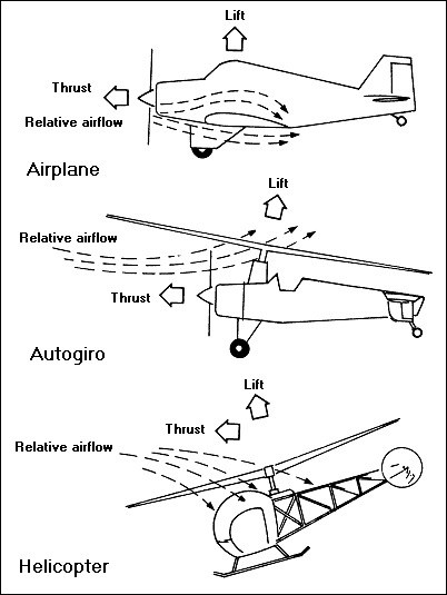
The airflow patterns created by the forward flight of an airplane an Autogiro, and a helicopter are compared here. With the Autogiro, the rotor mast is inclined to the rear and the airflow into the rotor is from the front and below. In the helicopter, the rotor is inclined forward and the flow enters from above
There were other important benefits gained from experience with the Autogiro. The use of autorotation itself to turn an unpowered rotor pointed the way to a means of making a safe power-off landing in a helicopter. The late-model direct-control and jump-take-off giros of the 1930's went even further: improved systems of control to the rotor head, methods for making pitch changes to the blades, mechanical drive systems-all were developed, and frequently by trial and error. Not that current methods are so very different. It is probably more true of helicopter design than any other phase of aerospace engineering that the personal element still enters into the equation. The creative process of designing a successful helicopter - particularly the rotor system — to this day has something in common with the free-for-all experimentation of the aeronautical pioneers. Although designers have created an impressive number of rotor systems, it is possible to narrow the field down to three basic types: articulated, semi-rigid, and rigid rotors. There are rotor systems that seem to fall outside this threefold classification, but for the most part these are only variations or combinations of the three types. In this connection, it should be appreciated that the term "rotor" or "rotor system" refers to a single unit only, composed of just one hub and the blades attached to it. A helicopter may have more than one main rotor; multiple arrangements of two, three, four or even more rotors have been found on various aircraft at different times in history, but each rotor is considered a separate system. For the purposes of the explanations that follow (which deal primarily with the various types of rotor hubs and the workings of cyclic pitch control) we will be concerned primarily with the most widely used type, the Sikorsky configuration, which has just one main rotor, in combination with a small tail rotor. The most important part of the system is the hub at the center. Here are concentrated all the forces generated by the movement of the blades through the air; aerodynamic, centrifugal, and inertia factors are involved that create very great loads which simultaneously pull the blades upward and outward. The hub is designed, for the most part, to accommodate and control these forces automatically, and the working of its mechanism is the very essence of the helicopter's mechanical nature. In dealing with the three basic types of rotor systems we will describe how some of these forces affect the rotor hub. The articulated rotor system is the oldest; it appeared on the Autogiros of the 1920's and was incorporated in the first workable helicopters of the 1930's. (The Autogiro ancestry of the articulated rotor prompted an earlier name, the "Cierva rotor.") Today it is perhaps still the most widely used type, in one form or another.
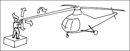
In a helicopter with an articulated rotor system, there are three kinds of movement for the rotor blade as it turns around the mast: up and down (flapping), back and forth in the horizontal plane (lead and lug), and changes in the pitch angle
In this system, exclusive of the rotation of the blades about the mast, each individual blade is attached so that it can move in three different ways about the hub. One movement is common to almost all helicopters and types of rotor systems: the turning of the blades along their span-wise axis, owing to the action of the pilot's controls, in order to change the pitch angle. The other two kinds of motion, however, are not under the pilot's immediate control. These are movements the blades make in response to the powerful natural forces acting on the rotor, for which the articulated hub provides the necessary mechanisms — specifically, hinges — which permit freedom of movement so the blades can "articulate," or flap up and down and move back and forth slightly in the horizontal plane. The pivot which permits the up-and-down movement is usually called the "flapping" hinge, while the fore-and-aft pivot, mounted vertically, which allows the blade to move back and forth slightly in the horizontal plane, is called the "drag" hinge.
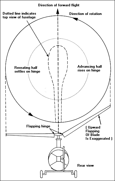
Flapping hinges in the rotor hub help to adjust the unequal lift forces in the right and left halves of the rotors circle as the helicopter moves through the air in forward flight. The hinges permit the blades to rise and fall as they turn, thus varying the angle of attack so as to equalize the lift forces
The flapping hinge provides the blades with flapping freedom, which permits each blade to rise and fall, as it turns, so the tip rides higher or lower in its circular path. While the hinge may be located very close to the center of the rotor drive shaft, it is more frequently designed to be a short distance from this center line. This is termed an "offset" flapping hinge, and it offers the designer a number of important advantages. The flapping motion is the result of the constantly changing balance between lift, centrifugal, and inertial forces; this rising and falling of the blades is characteristic of most helicopters and has often been compared to the beating of a bird's wing. One other point should be mentioned; the flapping hinge, in company with the natural flexibility found in most blades, permits the blade to droop considerably when the helicopter is at rest and the rotor is not turning over. During flight the necessary rigidity is provided by the powerful centrifugal force which results from the rotation of the blades; this force pulls outward from the tip, stiffening the blade, and is actually the only factor which keeps it from folding up.
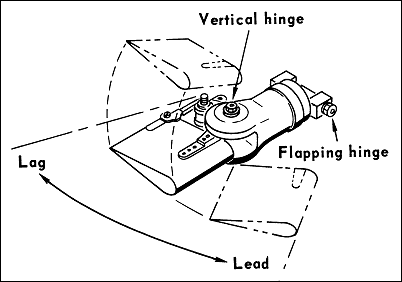
The flapping hinge permits each blade to rise and fall as it turns, and the vertically mounted drag hinge allows lead-lag motion
The vertically mounted drag hinge as we have already noted, permits each blade to move back and forth slightly in the horizontal plane independently of the movement of the other blades. The terms "dragging," "hunting," and "lead-lag" are also used to describe this movement, which is necessary to relieve the powerful forces that might otherwise bend and even break the blades. To prevent this back-and-forth hunting from developing into serious vibration, it is restricted by hydraulic dampers which slow down and "damp" the movement; this action is very similar to the damping effect of an ordinary hydraulic door-closer. The early Autogiros, incidentally, used friction discs to accomplish the same thing. The position that the blades actually assume while the helicopter is in flight obviously is the result of the various forces acting upon them. Normally, the blades will be lagged back slightly on the drag hinge and tilted up a few degrees on the flapping hinge; this upward tilt is termed the "coning angle" and is the result of the lifting force pulling upward on each blade while, simultaneously, centrifugal force is pulling outward. Since the centrifugal loading is so much greater, the blades only tilt upward a few degrees, and their path through the air takes the form of a shallow cone. The articulated type of rotor is designed to leave the blades as free as possible, to avoid trying to restrict their natural tendencies to flap up and down or move in the horizontal plane. One effect is that the blades can be very slender and light, since great strength is required only to resist the tension of the powerful centrifugal force pulling along the span of the blade. An articulated blade is designed to have the inertial, centrifugal, and aerodynamic forces developed in flight all balancing about the same point on the blade chord—this is ordinarily one-fourth of the way back from the leading edge, or, as it is called, the "quarter chord point." Balancing the forces in this manner makes it possible for the pilot to control the blades with a minimum of effort and tends to hold down vibration as well. These highly desirable characteristics are reasons why the traditional articulated rotor is still so widely used. The other two types of rotors are the semi-rigid and the rigid (or "hingeless"). Both are primary types currently in use, and both duplicate the function of the articulated rotor. Though different mechanisms are involved, the aerodynamic effects are essentially the same. In the semi-rigid rotor (sometimes called a "rocking hub" or "teetering" rotor), the blades are attached rigidly to the hub but the hub itself is free to tilt in any direction about the top of the mast. Although there is no lead-lag movement, the blades can still flap or, in the true sense, rock up and down in order to compensate for dissymmetry of lift when moving forward. Semi-rigid rotors have appeared on helicopters with two, three, and four blades and provide some simplification, although they cause other problems. One important advantage is the fact that there are no drag hinges, and therefore no drag dampers are required. But there are complications including the necessity for providing a type of universal joint between the drive shaft and the rotor hub. The rigid rotor, which until fairly recently was still in the experimental stage, is used in relatively few helicopters. In theory the rigid rotor is similar to an ordinary propeller; the blades are fixed to the hub without hinges and the hub in turn is fixed to the shaft. Of the various systems, it is closest to the elemental concept of the airscrew which tantalized experimenters in centuries past. (Obviously, there can be no such thing as a completely rigid rotor, since all blades inherently exhibit some degree of flexibility—from a structural viewpoint it would be almost impossible to build a truly rigid blade.) Since there are no flapping hinges, or any other provisions for movement at the hub, other systems have been developed to overcome the unequal forces on the rotor, including pre-coning and feathering of the blades. Pre-coning, as the word suggests, is an arrangement for presetting the blade at a slight upward angle from the hub to the tip. This is the same angle that the blade would ordinarily take, due to its coning upward in normal flight. If the upward tilt for average operating conditions is determined, and the blades mounted on the hub at this angle, the bending loads can be reduced materially. Pre-coning is thus a fairly simple design approach for dealing with the stresses on a semi-rigid or rigid rotor. Feathering, on the other hand, involves the incorporation of an entirely new mechanism in the rotor head. This system compensates for the lift differential between the advancing and retreating blades by reducing the angle of attack as the blade starts to rise and decreasing it as the blade starts to fall; this, of course, means that the blade has to be mounted on the hub, so that it can be rotated along its span-wise axis. As part of the system, the hub mechanism can be designed so the pitch changes are made automatically by the flapping (in this case the term "coning" is sometimes used, as well) of the blades as they turn. As the blade starts to flap, it activates linkage which changes the blade's angle of attack. This technique has been incorporated in many modern helicopters; the arrangement has been called "pitch-cone coupling." The semirigid and rigid rotor systems represent attempts to simplify helicopter design, but the end result more often than not has usually been the need for added complications such as pre-coning or pitch-cone coupling, which tend to defeat the designer's original aim. This pattern has been repeated over and over again in the development of new rotor systems and of other parts of the helicopter, as well; the designer succeeds in simplifying one mechanism and finds that he has to add another device somewhere else in the system. The problem of trying to reduce complexities that refuse to be banished has plagued designers since the days of the first helicopters. One experimenter, D. H. Kaplan, in writing of the intricacies of the rotor cyclic control system, summed up one part of the puzzle thus: "In a cyclic-controlled rotor, every time the designer tries to deny the blade a freedom, it demands compensation somewhere else in the rotor mechanism. The history of the helicopter is filled with attempts to reduce complication... invariably this turns into a game of Chinese checkers as the designer feverishly moves the complicated problem from one part to another, never getting rid of it." As with the other mechanisms found on a modern helicopter, the rudiments of the cyclic system can be traced back to the Autogiro, on which the first effective rotating-wing controls were developed. The designers of the first Autogiros of the early 1920's did not attempt to control the rotor blades directly. Instead, conventional airplane-type controls were furnished-rudder, elevators, ailerons mounted on stub wings—and the rotor was controlled by the aerodynamic forces on these surfaces. Since the ailerons were outside the propeller slipstream (the direct blast of air from the propeller), at low airspeeds they were the weakest link in the system; eventually a method was devised for obtaining lateral control by "rocking" the rotor hub from side to side. This meant that the ailerons and the stub wings that supported them could be dispensed with, and the wingless Autogiro appeared. The rocking head played a part in the development of cyclic pitch control systems. When the system was applied to some of the early helicopters, it was used for rocking the head not only from side to side but in all directions; in effect the hub was now mounted on a kind of universal joint. The idea was that by tilting the movable head (when the pilot moved his control stick) the axis of rotation would be inclined slightly from the vertical, and thus its lift would pull slightly in that direction. However, there were problems when this system was used with the power-driven rotor of a helicopter, caused by the drive shaft as it rotated the tilted hub. When the hub was tilted the mass of the rotor was no longer "on center" over the shaft, and this caused serious vibration. Also, very great control forces were needed to move the rotor head. The answer to this was the cyclic pitch control used on the majority of helicopters today. It had been discovered that you could get the same effect as rocking the hub by increasing the pitch of the blades in cycles as they rotated. As each blade swept through its full 360-degree circle, it changed pitch cyclically—that is, it assumed a high pitch at one point in the disc and then assumed a low pitch as it moved around to the opposite position. As the pitch was increased or decreased, the blades rose or fell on their flapping hinges, thus inclining the disc slightly from its vertical axis. The effect was that the tip path of the blades, as the rotor whirled around, was very much the same as it would have been with a rocking head rotor inclined in that direction. What made this approach particularly attractive was that at the time of this experimentation, many rotating-wing aircraft, helicopters and rotorplanes alike, were already furnished with collective pitch control. This was a system for changing the pitch on all blades to the same degree, simultaneously, in order to take off vertically, and the blades were therefore mounted on bearings so they could be moved for pitch control along the span-wise axis. All that was needed was the mechanical system for controlling the pitch of the blades cyclically as well as collectively. The device in a helicopter control system which accomplishes this, feeding the cyclic control movements to the rotor hub, is known by the rather interesting name of "swash plate." It is a doughnut-shaped unit that fits around the mast, actually consisting of two plates—an upper one and a lower one—with a bearing between the two. The upper plate is connected to the rotor hub by rods and consequently it spins around on the bearing as the rotor turns. The lower plate is linked to the pilot's cyclic control stick system and does not rotate. However this lower plate is mounted on pivots—either a spherical bearing or a gimbal ring—so that it can be tilted in any direction. As it tilts, the upper plate (which is moving in company with the hub) will be tilted as well. This results in a constant up and down movement in the link rods which connect the upper plate to the hub, accomplishing the cyclic pitch changes in the blades as they sweep around, and thus transmitting the pilot's control movements to the rotor. While it is not intended here to delve too deeply into the design of the cyclic control system, there is another factor which should be considered, since it helps explain the workings of the linkage from the swash plate to the rotor hub. This is called the "90-degree phase lag" or time lag. When the pitch of a rotor blade is increased, the blade does not immediately rise but has to rotate for approximately another 90 degrees (a quarter of a revolution) before it reaches the highest flapped position; thus, there is a lag of approximately 90 degrees, attributed to blade inertia and gyroscopic factors, between the point at which the pitch is increased or decreased and the point where the full effect registers on the blade. Most helicopters have the control linkage from the swash plate to the hub offset by approximately 90 degrees to compensate for this; the pitch change is fed into the rotor at a point one-quarter of a revolution early in the plane of rotation. For example, when the pilot pushes the cyclic control stick forward so as to incline the rotor forward, as each blade comes around it will receive the decrease in pitch at the 90-degree point on the right (advancing) side and the increase in pitch at the opposite point on the left (retreating) side. Because of the time lag, each blade is in its highest flapped position directly over the tail of the helicopter and its lowest flapped position directly over the nose. This, of course, inclines the rotor disc forward as desired to propel the helicopter into forward flight. In connection with the design of cyclic systems, one vital consideration is that the forces and loads acting on the tip of the blade are hundreds of times greater than the control forces which can be transmitted from the hub to the blade. The tip is going to go where it pleases, and the hub must be designed either to provide it with mechanical freedom through the use of hinges or, through structural flexibility, to move as it must under its dynamic loads. Even the so-called rigid rotor tends to behave like an articulated rotor because of the bending of the blades. (A blade rigid enough to resist these forces would be too heavy to fly.) There is one important structural rigidity, however, that is essential to the correct functioning of a cyclic control system. The blade must be constructed so that it will not twist when pitch changes are made at the hub; it must have what a designer calls "torsional rigidity." If the blade failed to have this stiffness it would not be possible to transmit the pitch changes from the hub along the span of the blade out to the tip. Nevertheless, as with many of the basic concepts in rotor design, there are exceptions to this rule. One important example is the torsionally flexible blade used on some helicopters. With this system a type of pitch control is used that requires a blade that is deliberately flexible in torsion. On these rotors the pitch control is accomplished by actually warping the blades through the leverage obtained from a small, controllable, aerodynamic surface mounted on the trailing edge of the blade, similar to the trim tab used on airplane control surfaces. C.Gablehouse "Helicopters and Autogiros", 1969 |

1. Helicopter Flight | 2. Flight Controls | 3. Autorotation | 4. Rotor mechanism


