
| Fairey "Jet Gyrodyne" 1953 |  |
 |
|
| Fairey "Jet Gyrodyne" 1953 | |
|
|
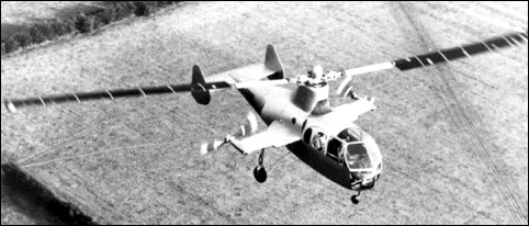
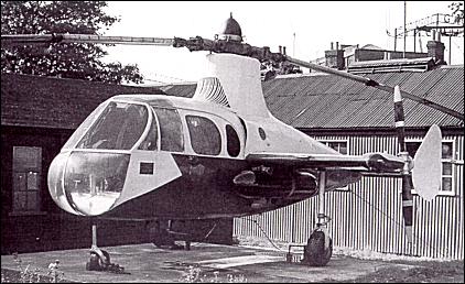
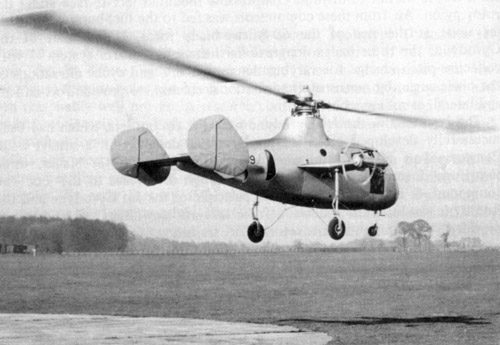
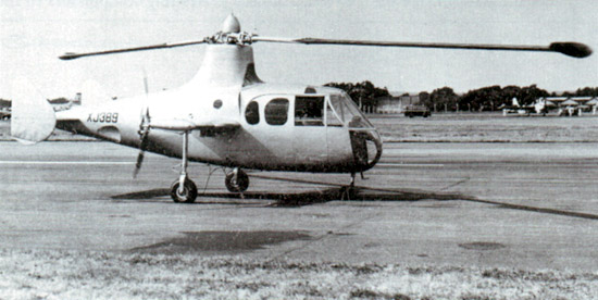
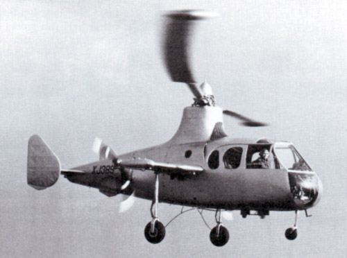
The Jet Gyrodyne, as the Fairey Gyrodyne was redesignated, was the subject of a Ministry of Supply research contract. Its function was to continue testing the tip-jet principle and develop procedures for the convertible helicopter, as represented by the Rotodyne. While the Jet Gyrodyne retained the basic appearance and engine of the earlier model, it had a two-bladed main rotor with pressure burners at the tips in place of the conventional three-bladed rotor, and at the end of the stub wings were two Fairey variable-pitch pusher propellers. These were driven by the Leonides engine which no longer drove the main rotor; instead, two Rolls-Royce Merlin compressors pumped air under pressure to the rotor tips. Tethered flights at White Waltham were followed by the first free flight in January 1954, but a full transition to horizontal from vertical flight was not achieved until March 1955. System proving continued and by September 1956, 190 transitions and 140 autorotative landings had been made. Although scheduled for scrapping in 1961, the Jet Gyrodyne was rescued and after a somewhat chequered history has been preserved. D.Donald "The Complete Encyclopedia of World Aircraft", 1997
The second Gyrodyne was radically modified to become the Jet Gyrodyne. The existing tractor propellers were changed to pusher configuration with variable-pitch propellers and the Leonides engine was altered to drive two centrifugal compressors fitted inside the rotor pylon which fed compressed air to fuel-burning jet units at the tips of the lengthened two-blade rotor. In this form, the Jet Gyrodyne made its first transition flight on 1 March 1955. Subsequent testing of the aircraft laid the ground for Fairey's major project, the Rotodyne. R.Simpson "Airlife's Helicopter and Rotorcraft", 1998 Towards the end of 1953 the surviving second prototype Gyrodyne reappeared in a very different form. Following a long period of test work with static rigs at White Waltham the principles and operation of the tip-jet rotor-driving system had been reasonably well proven. A research contract had been received from the Ministry of Supply, the basic layout of the Rotodyne had been settled and the time had come to try the principles in practice. This was necessary not only to continue the testing of the tip-jet, but to develop handling and other procedures for the compound, or convertible, helicopter. By early January 1954 this aircraft, named the Jet Gyrodyne — and carrying the compromised (that is duplicated) Ministry serial XD759, which was later to be changed to XJ389 - was making tethered flights at White Waltham in the hands of John N. Dennis, who had joined Fairey as helicopter test pilot in June 1949. The first free flight was made later in January. The Jet Gyrodyne retained the fuselage, tail unit, stub wings and tricycle undercarriage of the Gyrodyne, and was also powered by a specially modified Alvis Leonides nine-cylinder radial - but there the resemblance ended. The engine was used to drive, through a gearbox and shafts in the stub-wings, two variable-pitch pusher propellers of Fairey design. These propellers provided propulsion in cruising flight and slow-speed directional control through rudder pedals by means of a differential pitch-change which was superimposed on the collective-pitch action. To that extent the design was basically similar to that of the Gyrodyne - but a third drive from the Leonides was taken from the main gearbox, via a friction clutch, to two Rolls-Royce Merlin centrifugal compressors mounted face-to-face under the rotor pylon. Air from these compressors was fed to the fuel-burning pressure-jet units at the tips of the 18.29m two-blade rotor. Unlike that of the Gyrodyne, the rotor had a conventional helicopter control system - with collective-pitch change for varying the overall lift, and cyclic alterations of the blade-angle, by means of a conventional column, to provide fore-and-aft and lateral, or rolling, control. The key units in the Jet Gyrodyne were the tip burners, which had been successfully developed after failures by other designers in a similar field. Compressed-air from the blowers passed through the rotor blades, while centrifugal force fed the metered fuel through the blades to the jets. The compound, or convertible, helicopter principle of the Jet Gyrodyne and the Rotodyne was briefly as follows: Lift for take-off, slow flight and landing was provided by the jet-driven rotor. For transition to cruising flight the compressed air to the rotor tips was progressively reduced and available engine power transferred to the propellers, leaving the rotor as an auto-rotating lift unit which was supplemented (in a very minor proportion for the Jet Gyrodyne) by the fixed wing. The procedure was reversed for a return to the helicopter regime. All this sounds comparatively straightforward, but the operation was extremely difficult in practice until suitable drills had been established. The problem for the Jet Gyrodyne was accentuated by the fact that it was, at a gross weight of 2720kg, under-powered for the work it had to perform and the Leonides was normally operated at maximum boost. In fact, the Jet Gyrodyne could not quite maintain level flight in the cruising, autorotative, mode. The extent of the problem can be gauged from the fact that it was not until 1 March, 1955, that a transition was completed by John Dennis. This was the first time that a practical transition cycle in flight had been completed by any aircraft. Within four months of this first full transition, the techniques had become well established and transition was no longer being accompanied by a considerable loss of height. The cycle was demonstrated during the SBAC Display at Farnborough in September 1955; while practicing for this demonstration, 65 successful in-flight tip-jet re-lights were accomplished during eight days. Even during the earlier period of testing, the transition from helicopter to autogyro flight was relatively easy. The basis of the operation was, as already outlined, the transfer of engine power from the jet-feeding compressors to the propellers. The pitch of the propellers was progressively coarsened, thus absorbing more power and reducing the air delivery to the jets, which eventually flamed out, and the compressors were declutched. It was found that transition could be made at widely varying speeds, but 128km/h was found to be the most convenient, with a rotor speed of about 210 rpm. The really difficult operation was the transition back to helicopter flight. A great deal of flying was required before the best propeller-pitch and tip-jet re-lighting sequence could be established. A major part of the difficulty was that, with the compressors being driven, there was no reserve of engine power for the propellers during the re-lighting sequence, and the aircraft descended rapidly in autorotation until the jets had been re-lit. So long as the re-lighting was being done over or near an aerodrome there was no particular danger in this situation; a controlled landing could be made, and often was made, in autorotation. As finally established, the drill was to throttle back momentarily, engage the compressor clutch, switch on the tip-jet ignition and fuel supply, and progressively fine-off the propeller pitch. This automatically opened the intake-valves for the compressors. The tip-jets re-lit when a certain head pressure had been reached and collective-pitch was increased to keep the rotor speed down. Propeller pitch was then slowly reduced to zero so that maximum power was available for the blowers to give full tip-jet thrust. Because of the need to keep the gross weight down with the limited power available, the Jet Gyrodyne normally carried only sufficient fuel for 15 minutes or so of safe tip-jet burning endurance. Extra tanks were occasionally carried under the wings to provide 30 minutes' endurance, but, as already noted, there was no particular danger in fuel exhaustion for an aircraft which could make powerless autorotative landings from a best indicated gliding speed of only 72km/h. The high inertia of the big rotor allowed for a few moments of hovering before touch-down. By September 1956 the Jet Gyrodyne had made 190 transitions and 140 autorotative landings. The techniques were by then familiar and reasonably well understood, so that there was already a sound basis for the procedures required for the Rotodyne, which was to make its first flight a year later. That transition was not a hard-won trick by experienced test pilots was shown by the fact that some half-a-dozen Ministry of Supply pilots each flew the Jet Gyrodyne successfully after about an hour's instruction and practice. At the time when the Jet Gyrodyne was making its earlier test flights the design team was led by Dr G. S. Hislop, chief designer (helicopters), and Capt A. G. Forsyth, chief helicopter engineer, who was responsible, among other features, for the tip-jets, and shared with Dr J. A. J. Bennett (who had by then left the company) the 1949 British Patent on which the Jet Gyrodyne and Rotodyne concepts were based. Later Jet Gyrodyne flight development was carried out by Sqn Ldr W. R. Gellatly and Lt Cdr J. G. P. Morton, who were to take the Rotodyne through its four years of testing. H.A.Taylor "Fairey Aircraft since 1915", 1974
| |||||||||||||||||||||||||||||||||
|
|
|
|


20
reply