The Curtiss-Wright X-19 started life as a commercial venture to develop a small, 4-passenger, executive VTOL aircraft that would have good high speed performance. Funded initially by Curtiss-Wright, it was designated the M-200 (references vary, some calling it the X-200). The M-200 was a very innovative aircraft with which Curtiss-Wright would attempt to re-enter the aircraft business. Unfortunately, it proved to be their last try.
The Curtiss-Wright Company was formed from the merger of the companies started by aviation pioneers Glenn Curtiss and the Wright Brothers. Curtiss-Wright was a major aircraft manufacturer through World War II, but after the war they never won another production contract and gradually entered other markets. By 1952, they even disbanded their aircraft design and manufacturing division.
However, Curtiss-Wright remained a giant in the propeller business. In 1958, Curtiss-Wright engineers envisioned the idea of using a propeller's radial lift to generate the lift required to fly at low forward speeds and up through transition. The prop not only would propel the aircraft forward, but also would provide lift during forward flight. This would free the aircraft from having a wing sized for low speed flight. With a practical application of this concept, Curtiss-Wright hoped to reenter the aircraft market,
To explain radial lift simply, think of a propeller turning on a shaft pointed straight into the air flow. In this case, each blade of the propeller strikes the air flow in exactly the same way. However, when the propeller shaft is at some angle relative to the airflow, the blades are not loaded evenly, as it would be if moving straight into the wind. This is because the blade moving down is at a higher angle of attack than the rest of the blades. The net result is a force, called the radial lift, which is perpendicular to the shaft and pointing upward. Obviously, a propeller produces a large amount of thrust in the direction parallel to its rotating shaft. Radial lift is in addition to this thrust force. All propellers produce radial lift that in general is thought of adversely. But, in theory, if the propeller is designed properly, radial lift could provide enough lift to completely support an aircraft. The amount of radial lift that can be produced is a function mostly of the blade width and twist, accounting for the wide, highly twisted shape of the X-19's props.
To confirm the radial lift principal, Curtiss-Wright built and flight tested an experimental VTOL aircraft called the X-100. With solid test results confirming their theories regarding the potential for a practical application of radial lift, Curtiss-Wright pressed on with the design of the M-200. In theory, the wing could now be sized for cruise flight, since the radial lift produced by the props would provide a significant portion of the total lift needed at low speed. Numerous design trade-off studies were performed which ultimately led to the X-19's tandem wing configuration with a tilting propeller at each wing tip.
It is interesting to note that the X-19 was built from the propeller designers' point of view. As a propeller manufacturer, Curtiss-Wright long had observed that in most cases the aircraft designers did not consider propeller requirements until long after an aircraft's configuration was frozen. The consequence was that the prop had to fit into other aspects of the aircraft design that already were fixed, with the resulting propeller design often being far from optimum. Thus, the X-19 started with what Curtiss-Wright engineers felt was the optimal design for a propeller for a VTOL aircraft and then built the aircraft around it. The propellers had a somewhat awkward appearance, being very wide with a large amount of twist. This allowed them to maximize the amount of radial lift.
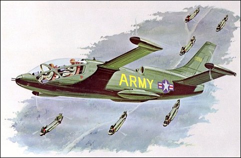
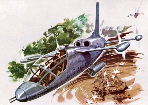
At the start of the program, Curtiss-Wright funded the entire effort, with no interest in any government support. Two prototypes were being built when new management at Curtiss-Wright decided they no longer wanted to invest company research funds. They decided to offer the two aircraft to the Tri-Service VTOL Program, a joint Air Force, Army, and Navy program office tasked with developing VTOL technologies for military needs. The Tri-Service Program also was developing the XC-142 and the X-22. It took eighteen months of trying until the Air Force agreed to buy the aircraft. Curtiss-Wright's interest in the effort was fading rapidly, and the Air Force's decision to buy the M-200s came on the morning that the board of directors was meeting to make a decision on continuing the program. When the Tri-Service Program bought the X-19s, the two prototypes already were 55 percent and 35 percent complete, with a substantial investment already having been made by Curtiss-Wright.
The original X-19 design, as the M-200, was not built to any specific mission requirement. The goal was to fly as fast and far as possible and to be economically competitive with conventional executive transports that were becoming very popular in the 1960s. Analysis of the design showed that the M-200 could achieve a range of 1450km to 1850km with a maximum level speed of 740km/h at 4880m. It was to conform to FAA regulations, have all weather flying capability, low noise level, and be free of vibration. Conventional aircraft construction techniques and materials were used.
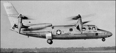
The X-19's basic configuration was an all-metal, monocoque fuselage, with two shoulder-mounted tandem wings. A nacelle at each wing tip could rotate from pointing vertically for take off and landing to pointing horizontally for cruise. The wide, specially-designed propeller was mounted in front of each nacelle. Two turboshaft engines housed in the rear fuselage powered the four props. The fully hydraulic tricycle landing gear retracted completely into the fuselage. A large vertical tail was required because the props were located relatively close to the fuselage. Total height was just over 5m.
The original fuselage was 12.5m long, but the cabin area was small... only 1.2m high, 1.4m wide, and 2.4m long. The passenger compartment was intended for four passengers, or 450kg of cargo. The cabin was pressurized to 4880m. Maintaining pressure to a greater altitude would have added too much weight. All fuel was stored in the fuselage, aft of the passenger/cargo area. There were two 860-l tanks and one 990-l tank.
The front wing had a 6.1m span with a narrow chord, while the rear wing had a 6.4m span with a greater chord. The rear wing had almost twice the area of the front wing. The wings had no incidence, dihedral, or sweepback. The front wing incorporated full span flaps, while the rear wing had inboard ailerons and outboard elevators, the ailerons being slightly larger than the elevators. The flaps on the front wing were directly coupled to the nacelle tilt angle, and the pilot could not control them independently. At hover, the flaps and elevators drooped to their full extension of 60 degrees to decrease the amount of wing area that was in the prop downwash. The location of the props on wing tips, however, resulted in the loss of 7 to 9 percent of lift due to wing interference.
Curtiss-Wright intended originally to use four Wankel rotary engines rated at 580hp each, with the capability to still operate vertically when one failed. The Wankel engine was attractive because it could hold sea level power up to 6100m. Curtiss-Wright wanted to control the manufacturing of all major components that would go into the aircraft and purchased rights to the Wankel engine for North America, as well as aviation rights worldwide. However, they could not get a favorable licensing agreement from the manufacturer. Curtiss-Wright eventually abandoned the Wankel in favor of two Lycoming T-55-5 turboshaft engines of 2200hp each (although some sources stated T-55-L-7 engines of 2650hp each). This more than doubled the total power, but retained the ability to operate with one engine failed, including performing vertical take-offs and landings. Switching from four engines to two also simplified the design by decreasing the engine interconnects, and changing to turboshaft engines eliminated the need for engine cooling. Power from the engines was distributed to the props by means of three-inch diameter drive shafts and seven gear boxes. The gear boxes consisted of one engine coupling box that coupled the two engines so that either could power the entire system, two T-boxes to transfer power from the fuselage shafts into the wing shafts, and four nacelle tilt gear boxes. The exhaust pipe from each engine joined in the fuselage so that only one pipe exited the rear of the aircraft.
The 4m diameter props had a unique appearance, as previously discussed, being optimized for the production of radial lift. Their construction consisted of a steel shank, foam core, and fiberglass shell. This innovative, light-weight construction was needed because conventional metal props with the required design would have been too heavy. The paddle-wheel shape allowed them to produce about 2.7kg of thrust per horsepower, a relatively large amount. Low prop noise was obtained because the maximum tip speed of 250m/s was well below sonic speed.
The cockpit accommodated two pilots seated side by side. The aircraft could be flown from either seat, but the pilot-in-command seat was on the right, as in a helicopter. The cockpit resembled that of a conventional aircraft, with the cockpit visibility being very limited for a VTOL aircraft. The high instrument panel also restricted vision over the nose. Two one-foot square windows were located near the pilots' feet, but were too small to be effective and later were modified into ram air inlets to provide additional cooling. Each pilot had a conventional stick, rudder pedal, and two throttles. Nose wheel steering was by means of a hand tiller controlled by the copilot.
To minimize the clutter on the instrument panel, there was a single oil temperature gauge and single oil pressure gauge for all nine gear boxes. The pilot could select which component to monitor by rotating a 9-way selector switch to the desired component. To signal a problem, each gear box had a single warning light that indicated either high or low oil pressure, or the presence of metallic chips in the oil. If the light illuminated, the pilot had to rotate the 9-way switch to see the specific problem.
When rotated to the vertical positions, the front nacelles rotated past vertical, to 97 degrees, meaning the thrust actually pointed slightly forward. The rear naceltes rotated only to 82 degrees with their thrust pointing slightly rearward. A tilt button on the control stick caused all nacelles to tilt together. Initially, the nacelle tilt rate was mechanized at 5 degrees per second. It was soon realized that this would have required a deceleration from 90km/h to hover in less than 5 seconds, resulting in 0.5g of longitudinal acceleration. This was too much, so the rate was reduced to 1 degree per second, resulting in a more reasonable 0.2g. Two independent hydraulic systems controlled the nacelle rotation and prop blade angles. If the automatic system failed, the pilot could rotate them manually using a hand crank. The crank required 570 turns to move the nacelles from end to end, and eventually was replaced with a motor.
The Tri-Service Program required a few changes to convert the M-200 into the X-19. North American Aviation LW-2B ejection seats, which used a rocket catapult mechanism and ballistically deployed parachutes, were added. These seats could operate from zero altitude and zero airspeed up to 15250m and deploy fully within 0.5 second from seat firing. The seats ejected through the canopy. The fuselage was lengthened by 0.9m so that two more passenger seats could be added, bringing the total personnel load up to two pilots and six passengers. This increased the fuselage length to 13.5m. The cabin door was enlarged to 1.06m high and 1.17m long, and a rescue hoist was added. The resulting aircraft was a bit long for a six passenger aircraft, but this was attributed mostly to the engines and fuel tanks being located in the fuselage. The only difference between the two prototypes was that the second had better instrumentation and data recording, and also had a dummy refueling probe installed on the nose to evaluate probe and drogue in-flight refueling.
Weight growth after adding the ejection seats and stretching the fuselage resulted in the useful load being reduced to 185kg. This allowed for only one pilot and fuel for 10 minutes of hovering. With two pilots, the hovering time was cut to 1 minute. However, there was still 270kg of unusable fuel because of the location of the fuel pumps inside the tanks. The pump position was changed to improve the amount of usable fuel.
The X-19 was statically unstable in hover and in pitch and roll at low speed, mandating the addition of stability augmentation in both of these axes. Control by the augmentation system was limited to 30 percent of the pilots' control authority, so the pilot could override it if necessary. No stability augmentation was needed for yaw. The system initially mechanized rate feedback, but initial testing showed this to be of little use to pilot. The system was changed to a rate plus integral of rate, which improved control for hover and low speed flight. The X-19 was test flown with the stability augmentation turned off. Although it was controllable by the pilot, the workload was unacceptable.
The X-19's "Achilles' Heel" proved to be its gear boxes. All gear boxes were designed to absorb the power required to lift the aircraft at a maximum weight of 5540kg. Great difficulty was encountered in qualifying them, and very low life limits were established in order to conduct flight tests.
The engine coupling gear box, which combined the power output of the two engines, was capable of absorbing 2.900 horsepower with both engines running, or 2500hp from only one engine. With each engine producing 2200hp (or 2650hp, depending on the reference), the gear box obviously could not absorb full power from both engines. In addition, it was limited to 50 hours of operation. Likewise, the nacelle gear boxes had estimated lives of 13-14 hours and were thus limited to 5 hours of operation. The problem was felt to be improper heat treating of the gears.
Wind tunnel tests of the initial design indicated an unac-ceptably high amount of interference drag at the junctions of the wing/fuselage and wing/nacelle. Drag clean up measures were taken, and more wind tunnel tests were run to confirm the improvement. The rear wing had significant lift loss due to downwash from the front wing, but knowing this, it was compensated for in the basic design. Airframe structural tests revealed no major problems. Full scale static propeller tests were performed to evaluate and reduce download losses on the wing at hover.
The intended design empty weight was 3600kg with a gross take-off weight of 5540kg. However, the empty weight grew to 4800kg and the gross take-off weight to 6160kg by the time the aircraft was built, thus reducing the useful load and placing greater stress on the gear boxes. Most of the weight growth came from the fuselage, wings, and power transmission system. It is safe to assume that Curtiss-Wright engineers started their fuselage and wing designs using standard practices for a conventionally configured aircraft, but stress analyses indicated weaknesses peculiar to the tandem design and prop locations. The fuselage had to be heftier than originally expected to handle the loads imposed by the landing gear location and the tandem wing configuration. The wings also had to be heftier than normal because during hover, all lift came from the props at the wing tips, rather than the lift being distributed along the wing as on a conventional aircraft. Also, the wings had to be very stiff so as not to transmit any propeller vibration. The shafting and gear boxes also proved to be heavier than predicted.
Altitude was controlled during hover by the throttle, and precise control was difficult because of a lag of nearly one second in the engine response time. Varying the pitches of the four props controlled pitch and roll. A unique prop rotation scheme was used to maximize propeller torque for yaw control...the props on opposite corners turned in the same direction. A yawing moment resulted from the blade angle being increased on one corner and decreased on the opposite corner. The pilot didn't control the blade angles directly, but used the rudder pedals for yaw and the stick for pitch and roll inputs. A mixer in the flight control system automatically controlled the actual commands to the individual props.
To initiate a transition from hover to horizontal flight, the pilot pressed the tilt button on the stick to start the nacelles rotating, then added throttle to increase lift, accelerate, and maintain altitude or climb. As altitude and speed increased, the pilot continued to lower the nacelles until reaching 295km/h, at which time the transition was complete and the X-19 would fly like a conventional aircraft. Throughout the transition, the mixer continuously faded out prop control and faded in conventional control surface control as the airspeed increased. To reverse the transition, the process was reversed.
Roll out of the first prototype, tail number 62-12197, occurred on July 23, 1963. The flight test approach was to demonstrate hover, transition, and finally forward flight. Curtiss-Wright pilots would fly the initial flights, demonstrating hover and transition. After that, a Tri-Service test team would take over.
The first flight was performed on November 20, 1963, at Curtiss-Wright's facility at Caldwell, NJ. The X-19 lifted off for only a few seconds in hover before settling and collapsing a main gear because of side loads. Although the damage was minor, it was seven months until the X-19 flew again.
After this first accident, the Air Force and Curtiss-Wright debated over where flights should be performed. The Air Force wanted to send the X-19 to Edwards AFB. Curtiss-Wright argued that supporting the test program at Edwards would be difficult, and that in an emergency, the X-19 would land vertically, making the long runway and large dry lake bed unnecessary and a waste of taxpayers' money. The Air Force finally agreed that flights up through transition would be done at Caldwell, NJ, but the remainder of test flights would be performed at Edwards.
Flight testing resumed on June 26, 1964. The X-19 made numerous hovers, most only a few seconds in duration. By August 7, it had flown on twelve different days and accumulated one hour and 37 minutes, accomplishing most of the objectives planned for its first eight hours of hover testing. The X-19 demonstrated spot turns, lateral translations at speeds up to 28km/h, rearward flight at 19km/h, forward flight at 37km/h, and 50 take-offs and landings. This may sound meager compared to testing fixed wing aircraft, but was consistent with the way helicopters were tested.
During these tests, the X-19 proved difficult to control, requiring excessive pilot workload. Various combinations of stick breakout and gradient forces were tried, but produced no improvement. However, the pilots were improving their skills at such a fast rate as they gained experience that it was difficult to determine if improved performance was from increased experience or the control system improvements.
On the 21st flight, the stability augmentation system was turned on, which made hovering much easier. Flight speeds up to 160km/h were obtained with good flight characteristics up to this speed.
On November 12, the X-19 experienced a full pitch hardover caused by the stability augmentation system. The pilot retained control because of the limited authority of the stability augmentation system and deactivated it. On the next day, they experienced a roll hardover. The cause of these incidents never was determined conclusively.
On December 4, 1964, the X-19 suffered damage from loose cinders on the runway, which had just been resurfaced. Both engines and the leading edges on all four props were damaged. On January 31, 1965, one prop failed, which forced suspension of further testing for six months.
While repairs were being made, it was decided that testing should be moved to the Federal Aviation Administration's National Aviation Facilities Experimental Center (NAFEC) near Atlantic City, NJ. On July 31, 1965, the X-19 hovered for an air worthiness test after six months of down time, following which the props were removed and the aircraft was shipped to NAFEC.
The X-19 was reassembled quickly and soon was flying again at NAFEC. Throughout August 1965, it made numerous high speed hovers going more and more into the transition. At this point, the Air Force test team joined the program. The Air Force test pilot quickly determined that the remaining control problems during hover were caused by excessive and uneven hysteresis in the control stick. Hysteresis is the tendency of the stick and control surfaces not to return to their original position when the pilot moves the stick then lets go (it is caused by friction between all the moving parts and stretching of control cables). Pitch hysteresis was found to be 4 to 8 percent of total displacement, and lateral hysteresis was 12 to 25 percent. Pilots had to make much bigger roll inputs than pitch inputs, resulting in poor control harmony and the pilot getting out of phase with the aircraft's motions. This problem was corrected, and hovering became much easier.
The first full transition was planned for August 25, 1965, on flight number 50. As the X-19 climbed and accelerated, the nacelles tilted as far as 65 degrees from vertical as the aircraft reached 150km/h at 400m. At this point, the temperature warning lights for left rear nacelle gear box and aft T-box illuminated. The pilots terminated the test and began a return to the airport. An immediate, emergency landing did not appear warranted, and the pilots planned a normal approach based on the recommendation from the ground support team. As they circled to line up with the preferred runway, a very high frequency vibration and a low frequency random shake began. Lateral control began to deteriorate. With the X-19 pointed toward a wooded area at low altitude and fearing that they would not clear the trees, the copilot jammed the throttles forward. As they climbed and accelerated, some control was regained and the vibrations smoothed out. At 120m, the left rear prop snapped off, and the X-19 rolled to the left and pitched up. This was followed promptly by the separation of the left front prop, then the two right props. The pilots bailed out inverted, their parachutes deploying fully within 2 seconds at an altitude of 70m. The aircraft crashed into a nearby swampy area and was totally destroyed. The pilots suffered only minor injuries, mostly cuts from ejecting through the canopy. The time from loss of props to ejection was only 2.5 seconds. The cause of the crash was attributed to the copilot's applying full power. The drive system could not absorb the 4400hp being generated, resulting in the failure of the prop gear box. Total flight time for the flight was only seven minutes.
The crash itself did not end the X-19 program. The Air Force wanted to continue with testing the second prototype, which was nearing completion, but wanted to switch to a fixed price contract. Curtiss-Wright did not like that, because they would now take all financial risk. Their management also saw no future business in a commercial VTOL transport, even if the X-19 ultimately proved successful. They refused the Air Force's offer. Unable to come to any agreement, the program ended in December 1965.
The X-19 completed 129.4 hours ground running time and flew a total of 3.85 hours. The second X-19 never flew and eventually was cut up for scrap.
An interesting side note can be made regarding the data that was available on the X-19. Typically, during the life of a program, numerous technical papers and journal articles are published. But, when a program terminates and the people scatter to other projects, press releases stop and little effort is made to document and preserve final results and lessons learned. If it exists, it usually is stashed on peoples' shelves, eventually shoved in boxes relegated to an attic or basement, and seldom entered into the technical library system. This hinders future researchers who try to learn from past successes and failures. The X-19 was a refreshing departure from this trend. Numerous papers were written and preserved, documenting both the accomplishments and lessons learned. Indeed, the length of this chapter and even the few conflicts in information is testimony to the vast amount of information that was preserved and found readily. It is especially noteworthy that some of these documents were written nearly twenty years after the program was terminated, indicating that the Curtiss-Wright engineers who worked on the X-19 program believed in the technology they developed and wanted their work to be remembered.
S.Markman & B.Holder "Straight Up: A History of Vertical Flight", 2000
The American armed forces had expressed an interest in this formula for reconnaissance, transport and tactical support, but the X-19's per-formance in the airplane mode was not brilliant. Despite a maximum cruise speed of 650km/h, its payload capacity was less than 550kg. The first pro-totype was quite badly damaged on its second flight in November 1963 and the second was never flown.